Raspberry Pi Raspbmc/XBMC/OpenElec (Media Centre)
Raspberry Pi (Model B+) (raspbian/openelec/xbmc)
CUCME/CME VBOX GNS3 IP Communicator basic LAB (VoIP)
Windows Server 2012 DC, DNS and AD
Understanding the Eight Basic Commands on a Cisco ASA Security Appliance
There are literally thousands of commands and sub-commands available to configure a Cisco security appliance. As you gain knowledge of the appliance, you will use more and more of the commands. Initially, however, there are just a few commands required to configure basic functionality on the appliance. Basic functionality is defined as allowing inside hosts to access outside hosts, but not allowing outside hosts to access the inside hosts. Additionally, management must be allowed from at least one inside host. To enable basic functionality, there are eight basic commands (these commands are based on software version 8.3(1) or greater).
- interface
- nameif
- security-level
- ip address
- switchport access
- object network
- nat
- route
Sample Network Diagram

interface
The interface command identifies either the hardware interface or the Switch Virtual Interface (VLAN interface) that will be configured. Once in interface configuration mode, you can assign physical interfaces to switchports and enable them (turn them on) or you can assign names and security levels to VLAN interfaces.
nameif
The nameif command gives the interface a name and assigns a security level. Typical names are outside, inside, or DMZ.

security-level
Security levels are numeric values, ranging from 0 to 100, used by the appliance to control traffic flow. Traffic is permitted to flow from interfaces with higher security levels to interfaces with lower security levels, but not the other way. Access-lists must be used to permit traffic to flow from lower security levels to higher security levels. The default security level for an outside interface is 0. For an inside interface, the default security level is 100. In the following sample configuration, the interface command is first used to name the inside and outside VLAN interfaces, then the DMZ interface is named and a security level of 50 is assigned to it.
ciscoasa(config)# interface vlan1
ciscoasa(config-if)# nameif inside
INFO: Security level for “inside” set to 100 by default.
ciscoasa(config-if)# interface vlan2
ciscoasa(config-if)# nameif outside
INFO: Security level for “outside” set to 0 by default.
ciscoasa(config-if)# interface vlan3
ciscoasa(config-if)# nameif dmz
ciscoasa(config-if)# security-level 50
ip address
The ip address command assigns an IP address to a VLAN interface either statically or by making it a DHCP client. With modern versions of security appliance software, it is not necessary to explicitly configure default subnet masks. If you are using non-standard masks, you must explicitly configure the mask, otherwise, it is not necessary.
In the following sample configuration, an IP address is assigned to VLAN 1, the inside interface.
ciscoasa(config-if)# interface vlan 1
ciscoasa(config-if)# ip address 192.168.106.1
In the following sample configuration, an interface VLAN 2, the outside interface is configured as a DHCP client. The use of the statement “setroute” tells the appliance to get its default route from the DHCP server.
ciscoasa(config-if)# interface vlan 2
ciscoasa(config-if)# ip address dhcp setroute
Configuring interfaces on 55×0 appliances
Notice on the screen capture from a Cisco ASA 5540 security appliance that the nameif command is used to name physical interfaces instead of VLAN interfaces.

switchport access
The switchport access command on the ASA 5505 security appliance assigns a physical interface to a logical (VLAN) interface. In the next example, the interface command is used to identify physical interfaces, assign them to switchports on the appliance, and enable them (turn them on). This command is not used on the ASA 55×0 appliances.
ciscoasa(config-if)# interface ethernet 0/0
ciscoasa(config-if)# switchport access vlan 2
ciscoasa(config-if)# no shutdown
ciscoasa(config-if)# interface ethernet 0/1
ciscoasa(config-if)# switchport access vlan 1
ciscoasa(config-if)# no shutdown
object network net-192.168.106
The object network net-192.168.106 statement creates an object called “net-192.168.106”. (You do not have to name the object “net-192.168.106”; that is a descriptive name, but you could just as easily name it “Juan”.) The network option states that this particular object will be based on IP addresses. The subnet 192.168.106.0 255.255.255.0 command states that net-192.168.106 will affect any IP address beginning with 192.168.106.
ciscoasa(config-if)#object network net-196.168.106
ciscoasa(config-network-object)#subnet 192.168.106.0 255.255.255.0
nat
The nat statement, as shown below, tells the firewall to allow all traffic flowing from the inside to the outside interface to use whatever address is dynamically (DHCP) configured on the outside interface.
ciscoasa(config)#nat (inside,outside) dynamic interface
route
The route command, in its most basic form, assigns a default route for traffic, typically to an ISP’s router. It can also be used in conjunction with access-lists to send specific types of traffic to specific hosts on specific subnets.
In this sample configuration, the route command is used to configure a default route to the ISP’s router at 12.3.4.6. The two zeroes before the ISP’s router address are shorthand for an IP address of 0.0.0.0 and a mask of 0.0.0.0. The statement outside identifies the interface through which traffic will flow to reach the default route.
ciscoasa(config-if)# route outside 0 0 12.3.4.6
In place of the manual default route configuration, as mentioned previously, you could instead configure your outside interface as a DHCP client and include the “setroute” statement to obtain the default route from the ISP’s DHCP server.
The above commands create a very basic firewall. A sophisticated firewall such as the Cisco ASA Security Appliance is capable of much greater functionality than what is shown here. These commands, however, will provide a solid foundation for configuring additional services on your appliance.
Other commands you might use include hostname to identify the firewall, telnet or SSH to allow remote administration, DHCPD commands to allow the firewall to assign IP addresses to inside hosts, and static route and access-list commands to allow internal hosts such as DMZ Web servers or DMZ mail servers to be accessible to Internet hosts. Of course, there are many more advanced commands that are explained in other how-to guides and in the book The Accidental Administrator: Cisco ASA Security Appliance: A Step-by-Step Configuration Guide.
Sample Base Configuration #1 (Static IP Address on Outside Interface)
ciscoasa(config)# interface vlan1
ciscoasa(config-if)# nameif inside
INFO: Security level for “inside” set to 100 by default.
ciscoasa(config-if)# interface vlan2
ciscoasa(config-if)# nameif outside
INFO: Security level for “outside” set to 0 by default.
ciscoasa(config-if)# interface ethernet 0/0
ciscoasa(config-if)# switchport access vlan 2
ciscoasa(config-if)# no shutdown
ciscoasa(config-if)# interface ethernet 0/1
ciscoasa(config-if)# switchport access vlan 1
ciscoasa(config-if)# no shutdown
ciscoasa(config-if)# interface vlan 2
ciscoasa(config-if)# ip address 12.3.4.5 255.255.255.0
ciscoasa(config-if)# interface vlan 1
ciscoasa(config-if)# ip address 192.168.106.1
ciscoasa(config-if)# route outside 0 0 12.3.4.6
ciscoasa(config-if)#object network net-192.168.106
ciscoasa(config-network-object)#subnet 192.168.106.0 255.255.255.0
ciscoasa(config)#nat (inside,outside) dynamic interface
ciscoasa(config)#exit
Note in the above configuration that the outside interface address and default route are configured manually. If your appliance’s outside interface is connected to a network with a DHCP server, such as an ISP, you could configured interface VLAN2 as a DHCP client with the command “ip address dhcp setroute”. The use of the “setroute” statement also eliminates the need for the manual default route configuration (route outside 0 0 12.3.4.6).
Sample Base Configuration #2 (DHCP-assigned IP Address on Outside Interface)
ciscoasa(config)# interface vlan1
ciscoasa(config-if)# nameif inside
INFO: Security level for “inside” set to 100 by default.
ciscoasa(config-if)# interface vlan2
ciscoasa(config-if)# nameif outside
INFO: Security level for “outside” set to 0 by default.
ciscoasa(config-if)# interface ethernet 0/0
ciscoasa(config-if)# switchport access vlan 2
ciscoasa(config-if)# no shutdown
ciscoasa(config-if)# interface ethernet 0/1
ciscoasa(config-if)# switchport access vlan 1
ciscoasa(config-if)# no shutdown
ciscoasa(config-if)# interface vlan 2
ciscoasa(config-if)# ip address dhcp setroute
ciscoasa(config-if)# interface vlan 1
ciscoasa(config-if)# ip address 192.168.106.1
ciscoasa(config-if)#object network net-192.168.106
ciscoasa(config-network-object)#subnet 192.168.106.0 255.255.255.0
ciscoasa(config)#nat (inside,outside) dynamic interface
ciscoasa(config)#exit
How to add ASA Firewall to GNS3
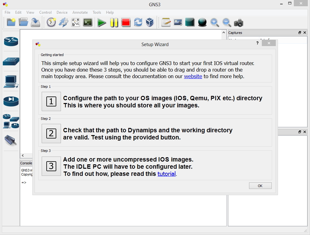
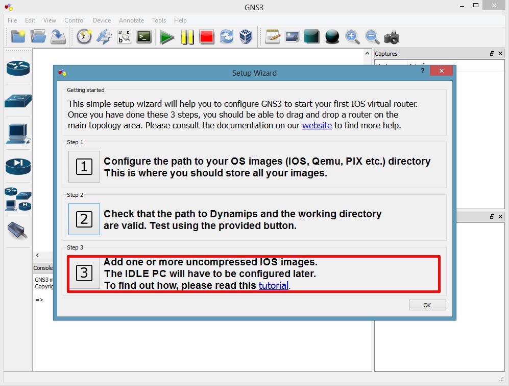
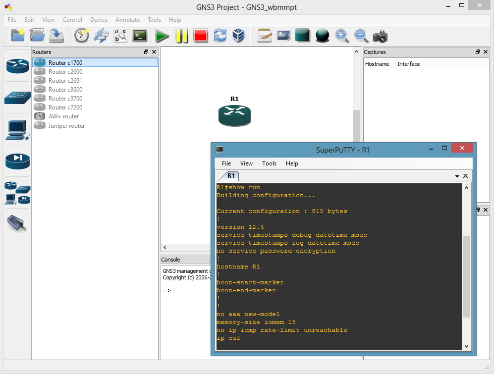
1. Download GNS3, I accept all the defaults (I actually tick to install SuperPuTTy, as tabbed console windows can be handy when using GNS3). Launch the program, you will be greeted with the following setup wizard. Select Option 1.
Note: You can do the same in future, by going to Edit > Preferences
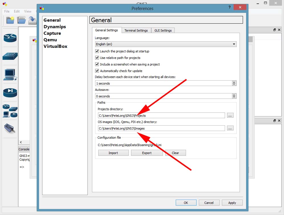
2. Check that the path to the ‘projects’ and your ‘images’ folder are where you want them to be. The defaults are fine but if you run GNS3 on several machines you might want to choose something like Dropbox > Apply > OK.
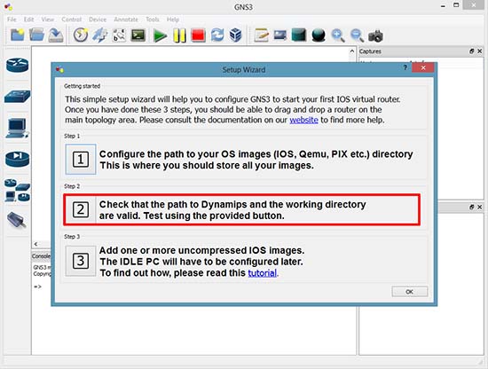
3. Option 2.
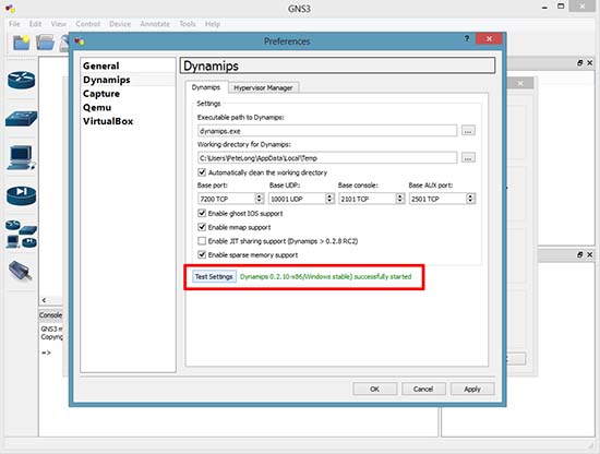
4. Click Test Settings > Have patience, it can take a couple of minutes > Apply > OK.
Adding Router Images to GNS 3
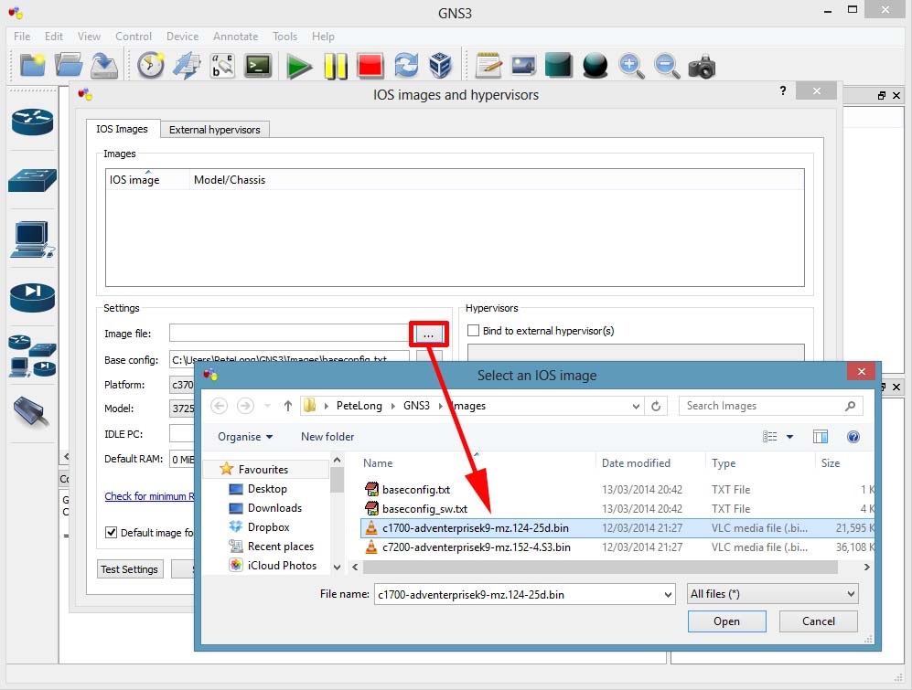
5. Option 3
Note: You can visit the same section in future by clicking Edit > IOS Images and Hypervisors.
6. Image file > Browse to the image you want to import. Here on GNS3 8.6 you can select the filename.bin file, with older versions you need to extract that file to a filename.image file.
Note: You need to legally download these images from Cisco. This means you need a CiscoCCO account, and a valid support agreement. DO NOT email me and ask for Cisco IOSimages, (I will just ignore you!).
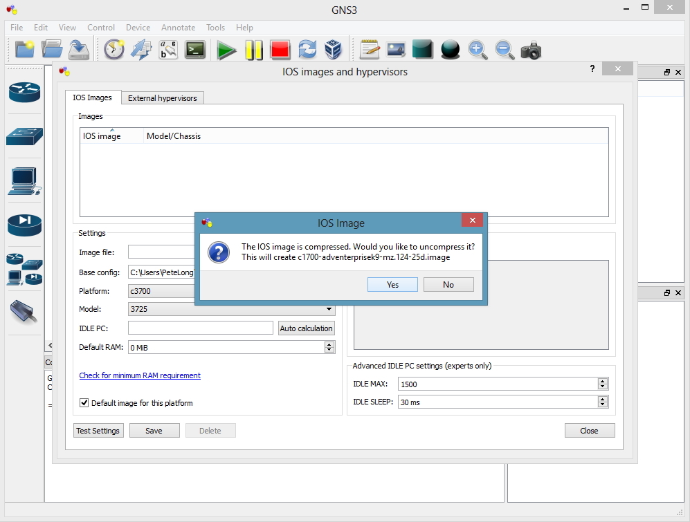
7. As mentioned above, it will convert my filename.bin image to an extracted filename.image file > Yes.
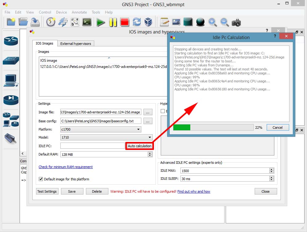
8. Set the Router platform and model > In the IDLE PC section click Auto calculation > This can take a while.
Note: You can do this later from the main workspace, and test a range of settings. I you don’t do this your virtual network devices will eat all your CPU power!
9. When complete click Close > Save > Close.

10. You can now start that model router to the workspace and use it. Repeat for each model of router you want to add.
Adding a Host to GNS3
Having a host machine for you labs is handy, usually you just need to be able to ping, or perform tracerts. So you can download a small Linux image from GNS3. There are a few options but I prefer linux-microcore.
11. Edit > Preferences.

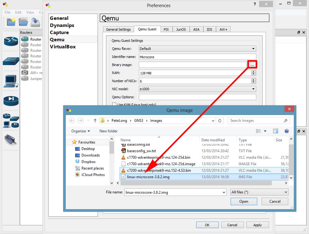
12. Quemu > Quemu Guest > Give it an identifier name (can be anything) > Browse to, and select the image you downloaded.
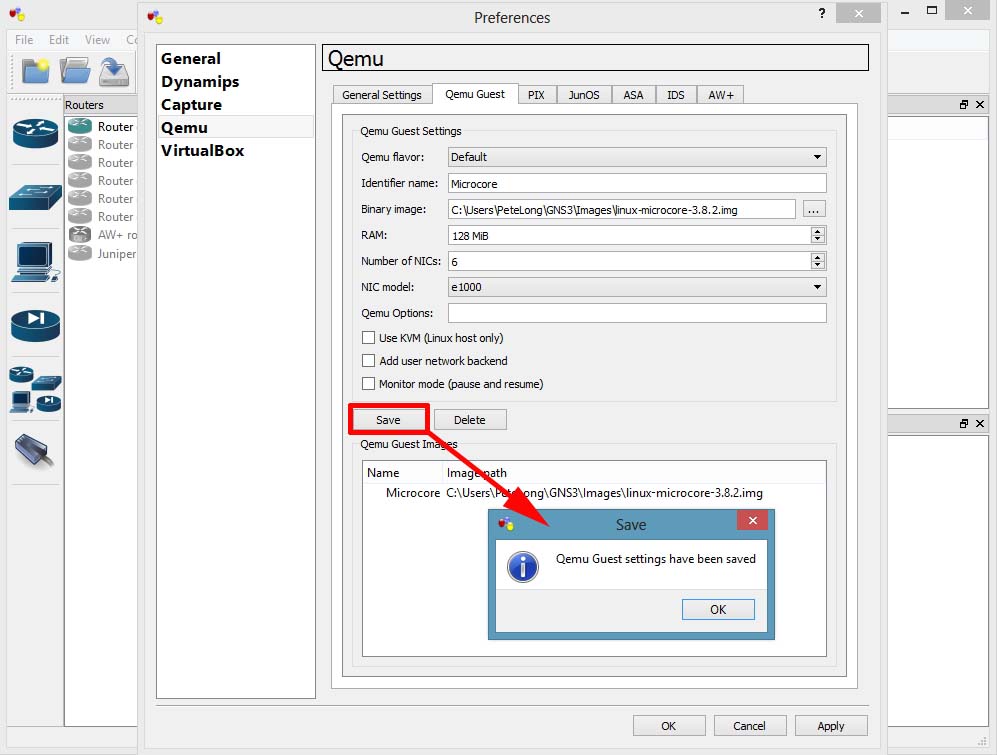
13. Save > OK > Apply.
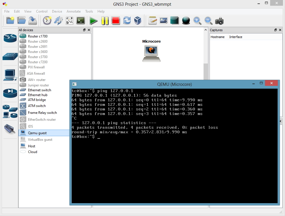
14. You can now drag a Quemu Guest machine onto the work space, and console into it.
Adding a Cisco ASA to GNS3
Yes you can add Cisco PIX as well, but there’s not many of them left in the wild.
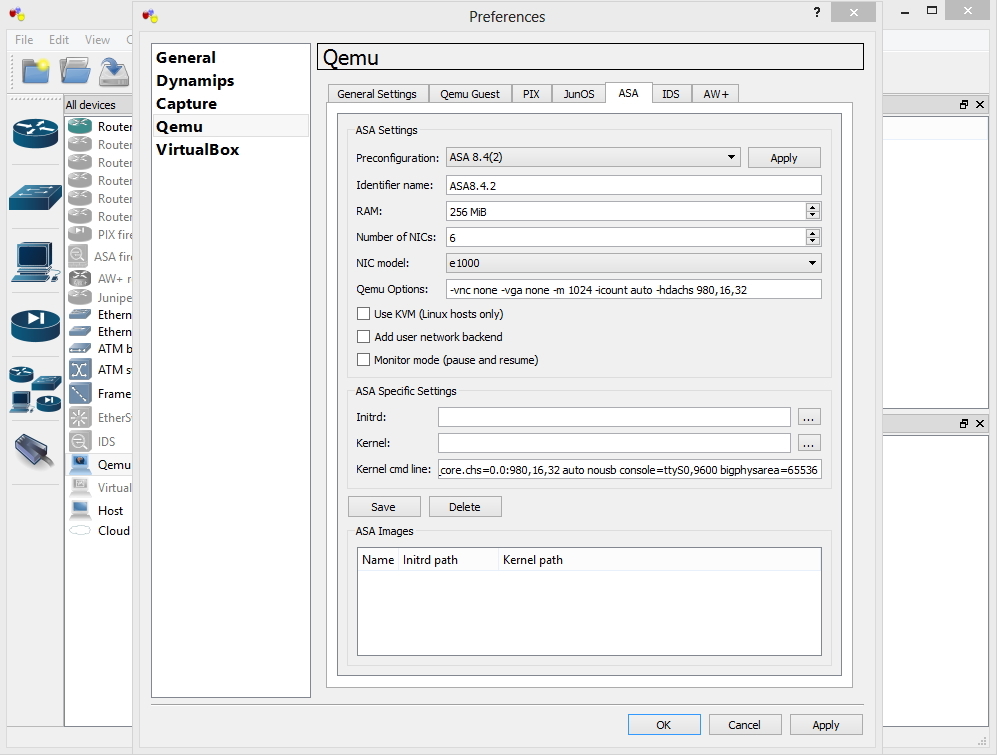
15. Edit > Preferences > Quemu > ASA > Give it an identifier name (can be anything) > Set the RAM to 1024 > Set the Qemu options to;
-vnc none -vga none -m 1024 -icount auto -hdachs 980,16,32
Set the Kernel cmd line option to;
-append ide_generic.probe_mask=0x01 ide_core.chs=0.0:980,16,32 auto nousb console=ttyS0,9600 bigphysarea=65536
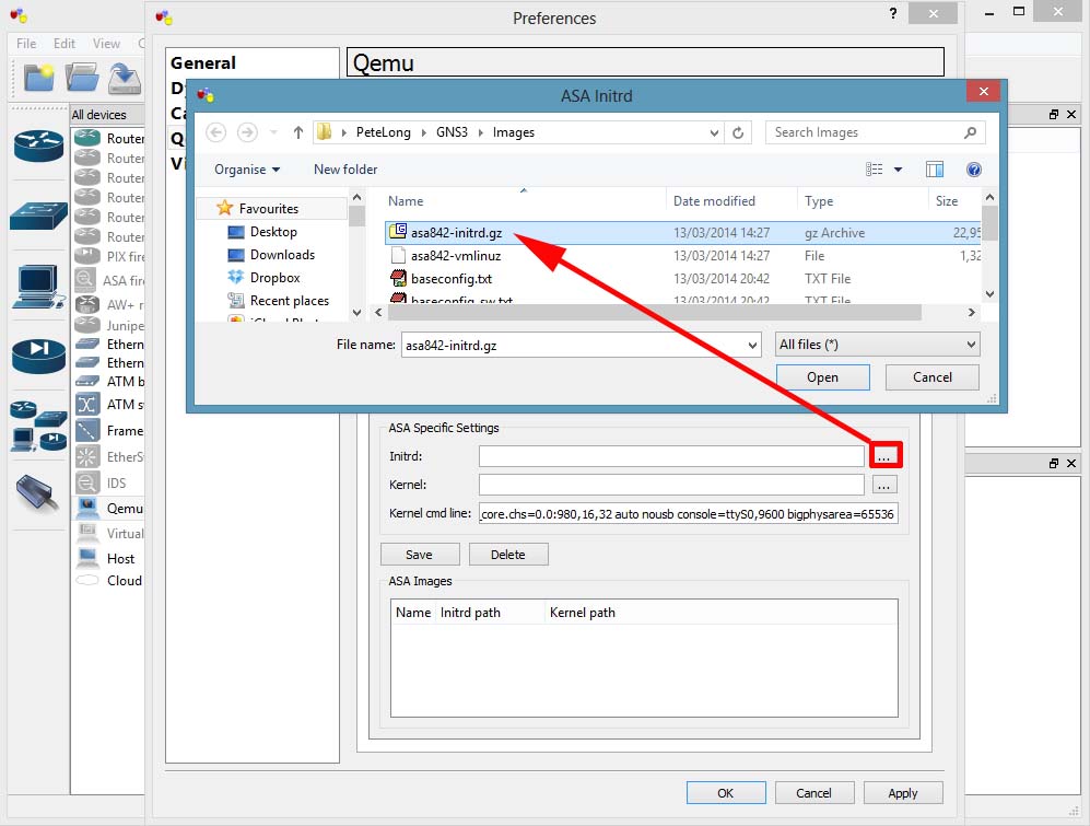
16. You need two files to run the ASA, an initrd file and a kernel file. You need to create these from a legally obtained copy of the asa843-k8.bin file.
Should you wish to locate these files form a less reputable source you are looking for
asa842-initrd.gz and asa842-vmlinuz, again don’t email me for them! If you are too stupid to use a search engine, then technical ninjary is not the correct career choice for you.
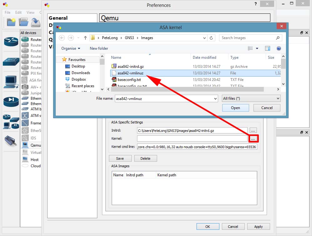
17. Finally select the vmlunuz file > Open.
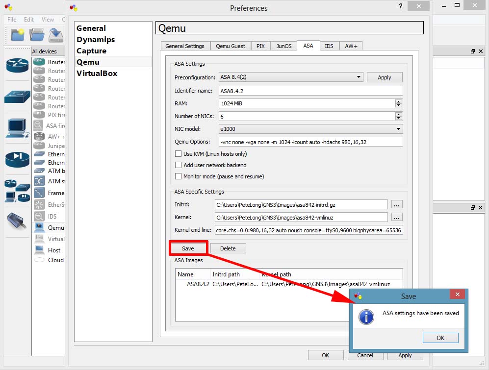
18. Save > OK > Apply.
19. You can now drag an ASA onto the workspace and console into it (it takes a while, be patient). When the ASA starts it has all the licenses disabled, to add them you need to change the ASA’s activation key. An ASA Activation key is usually linked to the serial number of the ASA, in this case we don’t have a serial number, (that’s not strictly true, if you check, it’s something like 12345678). So I will publish a working activation key*
*Disclaimer, this will only work on this virtual ASA, and it’s published elsewhere on the Internet, if I receive a request to remove it I will do so.
Another ‘quirk’ is every time you add a new ASA to the workspace, you need to go through this process, if you enter the commands below you can issue a reload and also save the ASA, without the need to re-enter the activation key.
activation-key 0xb23bcf4a 0x1c713b4f 0x7d53bcbc 0xc4f8d09c 0x0e24c6b6
{This can take 5-10 minutes}
copy running-config startup-config
{Enter}
copy startup-config disk0
{Enter}
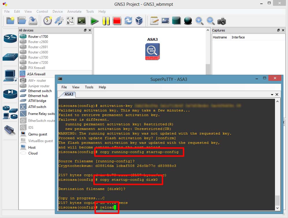
20. When it comes back up, (again it will take a few minutes). Your can check your ASA’s licensed features.


To Allow ICMP (Pings) from the inside Workstation as it will be blocked by default:
ASA(config)# class-map icmp-class
ASA(config-cmap)# match default-inspection-traffic
ASA(config-cmap)# exit
ASA(config)# policy-map icmp_policy
ASA(config-pmap)# class icmp-class
ASA(config-pmap-c)# inspect icmp
ASA(config-pmap-c)# exit
ASA(config)# service-policy icmp_policy interface outside
To Permanently save the ASA config in GNS3:
copy running-config disk0:/.private/running-config
copy disk0:/.private/running-config disk0:/.private/startup-config
conf t
boot config disk0:/.private/startup-config
Switches in GNS3
Ethernet Switch devices
 GNS3 with Dynamips help integrates an Ethernet switch that supports VLANs with 802.1q trunking. Trunk ports trunk all VLANs known to the switch – no VLAN pruning here. It is just a basic virtual switch with limited functionality that provides the very basics you’d want in a switch. If you drag an Ethernet switch onto the workspace, right-click it and choose Configure, you’ll see the options you may set.
By default, there are 8 ports in VLAN 1 configured as access ports. However, you may in theory have up to 10,000 ports and up to 10,000 VLANs. You are limited to either access ports or dot1q trunking ports.
You may connect the switch to the real world through a cloud device. The Console window in GNS3 may be used to show and clear the MAC address tables using the following commands:
show mac switch_name
clear mac switch_name
You can also see the MAC address table by right-cliking on your Ethernet switch and then choosing MAC Address Table.
If want greater functionality that the virtual Ethernet switch provides that is integrated into GNS3, then you’ll need to add a router with an EtherSwitch card.
EtherSwitch Cards
You can buy an EtherSwitch card that may be inserted into a router. The card will function similar to a switch. In GNS3 you may also insert an EtherSwitch card into a router slot. The 7200 series routers do not support this adapter but many of the router platforms available in GNS3 do. The EtherSwitch card that is supported is the NM-16ESW. Here is a list of some of the features supported by the NM-16ESW card.
- Layer 2 Ethernet interfaces
- Switch Virtual Interfaces (SVI)
- VLAN Trunk Protocol (VTP): domains, all modes (server, client and transparent), pruning and passwords.
- Trunking: 802.1Q only, no ISL, no dynamic auto or dynamic desirable mode.
- EtherChannel: no LACP and Pagp support. Manual configuration supported.
- Spanning Tree Protocol: simple STP supported but no MSTP, RSTP or other advanced stuff.
- Cisco Discovery Protocol
- Switched Port Analyzer (SPAN)
- Quality of Service: mls qos commands and mls qos maps are supported.
- IP Multicast Support
- Storm Control
- Flow Control
However keep in mind that this module works differently than a real Cisco switch and doesn’t support all the features of a Cisco Catalyst Switch. At this moment, it is not possible to emulate Catalyst switches with Dynamips/GNS3. This is due to the impossibility to emulate ASIC processors used in those type of devices. Please see the hardware emulated page for a complete list of missing features for EtherSwtich module.
Not all commands that exist on an actual switch are supported by the NM-16ESW card, but as you can see, using an EtherSwitch card gives you a lot more features than the integrated virtual switch. If you wish to use this card, I recommend that you download the documentation from Cisco’s official EtherSwitch module page. Only vlan database mode is possible (not the newer global configuration mode) and the show vlan command is show vlan-switch, for example.
To use the card, just add a router and include the NM-16ESW adapter or the EtherSwitch router device if you have configured a c3700 IOS image in GNS3.
VirtualBox and GNS3
VirtualBox
VitualBox is a cross-platform virtualization application very similar to VMware that runs on Windows, Mac, Linux or Solaris operating systems. VirtualBox provides a generic virtualization environment for x86 systems meaning it may run operating systems of any kind. Also, VirtualBox is usually faster and easier to use than Qemu, especially on Windows and Mac OS X. We recommend to read the manual for a complete understanding of VirtualBox and its features.
Creating Virtual Machines
First, make sure your have installed VirtualBox version >= 4.1, if not you can download it from the official website.
Then you can either create a new Virtual Machine using the Oracle VM VirtualBox Manager or download one of our appliance. The Linux Microcore 4.7.1 appliance has been imported for the following example.

Now you could create or import other Virtual Machines so you can get more than one VirtualBox guest in GNS3 but here we will create 2 linked clones instead. The concept of linked clone is quite simple, the new cloned VMs will be working with “linked” virtual hard disk and all new changes will be saved in a newly created disk, thus saving your disk space while all changes made in the clone VM will not affect the base VM.
To create a linked clone, right-click on your base VM, here Linux Microcore 4.7.1, and select the “Clone…” entry. Choose a name, reinitialize the MAC address of all network cards and finally the clone type. Repeat the process to create one more clone.


After completing the last configuration, you should see your 2 clones, named HostA and HostB in this example. You are ready to link your Virtual Machines in GNS3.

Using VirtualBox VMs in GNS3
Check that VirtualBox is functional in GNS3. Go to Preferences -> VirtualBox, check the path to vboxwrapper and click on the providedTest Settings button. You should see a message if everything goes well. You only need to do this the first time you setup VirtualBox support in GNS3.

Go to the VirtualBox Guest tab to add the VirtualBox VMs in GNS3. Choose an identifier name, a VM from the VM list (you may have to refresh the list using the provided button) and other options:
- Number of NICs is the number of network interface cards you will see inside your VM (e.g. ifconfig on Linux).
- Reserve first NIC for VirtualBox NAT to host OS is to you have your first network interface card (e.g. eth0 on Linux) configured with network address translation (NAT), allowing your VM to access your host network and Internet (if your host can access it of course).
- Enable console support to activate a serial console access to your VM. Please note that serial console support must also be configured on the operating system running in your VirtualBox guest for this feature to work. Here is a howto for Debian/Ubuntu Linux.
- Enable console server (for remote access) is to remotely access to your VM serial console. GNS3 creates a mini Telnet server that act as a proxy between the serial console and Telnet clients. This feature requires the Enable console support to be enabled.
- Start in headless mode (without GUI) will hide the VirtualBox graphical interface when the VM is started. This option is mostly useful if you have configured the previously described console support.

At this point, you should have added and configured your Virtual Machines in GNS3 Preferences. You can now add your VMs on the workspace, link them, start everything and console to all.

Once booted, configure valid IP addresses on both guest OS and ping between them. Here are the configuration used in this example:
HostA
tc@Linux:~$ sudo su
tc@Linux:~# ifconfig eth0 10.1.1.1 netmask 255.0.0.0
tc@Linux:~# ping 10.2.2.2
HostB
tc@Linux:~$ sudo su
tc@Linux:~# ifconfig eth0 10.2.2.2 netmask 255.0.0.0
tc@Linux:~# ping 10.1.1.1


Congratulations, you made your fist VirtualBox lab using GNS3!
Remote VirtualBox server
This is a more advanced topic that shows you how you can use a remote VirtualBox server. To do so, you first have to start vboxwrapper.exe or vboxwrapper.py (requires Python) on your server (VirtualBox must be installed too). By default vboxwrapper will listen for connections on port 11525, this can be changed using command line options (use vboxwrapper –help to display them all).
$ python vboxwrapper.py
VirtualBox Wrapper (version 0.8.4-RC4)
Copyright (c) 2007-2012
Jeremy Grossmann and Alexey Eromenko "Technologov"

Using VirtualBox 4.2.14 r86644
VBoxWrapper TCP control server started (port 11525).
Listening on all network interfaces
On your client, go to GNS3 Preferences, select Show VBoxWrapper Advanced Options, then disable the Enable VBox Manager one. Add an external VBoxwrapper which is the server IP address and port, 192.168.1.69:11525 in this example. Finally, hit the Test Settings button.

You should then see a similar message in vboxwrapper on your server if the connection has been successful.
Connection from ('192.168.1.69', 54906)
[Errno 54] Connection reset by peer
Finally, as showed earlier in this tutorial, add your VirtualBox guests and start using them as you would normally do. Remember that your VMs will run on a remote server and there will be no VirtualBox GUI on your client. This means you should have a way to access them and the easiest is either to configure console support or have a remote desktop (RDP) connection to your server.
Cisco IOS image for GNS3
Download Cisco IOS image for GNS3
Hi dear all, that’s really a great to share my hard work with you , After a lots of hit in Google I finally found trick to search Cisco IOS in free of course. So without talking much here are the link where you can free download Cisco ios image and you can upload or use this ios to the router and as well as in GNS3.
Small Collection of IOS Images.
ftp://ftp.unikon-ua.net/pub/Cisco/IOS/
{Updated}Big Collection of IOS Images (Almost All Cisco IOS Images)
ftp://62.117.115.92/upload/ios/
Another Big Collection
ftp://86.110.172.101/Soft/IOS/
(NEW)Cisco IOS Images Big Collection v3. **Direct HTTP Link**
http://www.jonsfiles.com/IOS%20Images%20for%20GNS3/Cisco_IOS_Collection/IOS/
http://www.intranet.betomt.com.br/repositorio/IOS/CISCO/ASA Binary files for GNS3
http://www.4shared.com/dir/5716575/72cbe353/IOS.html
New Big IOS Collection
